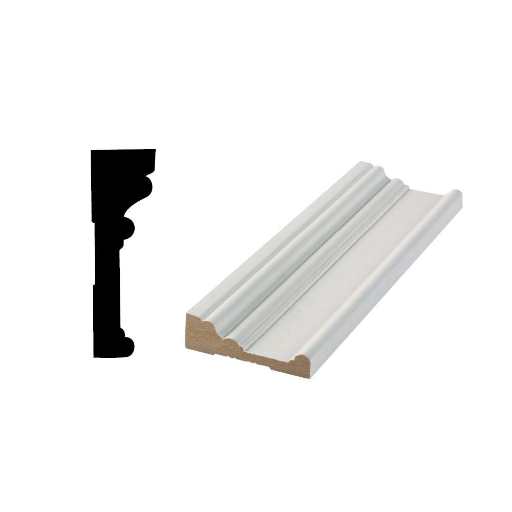
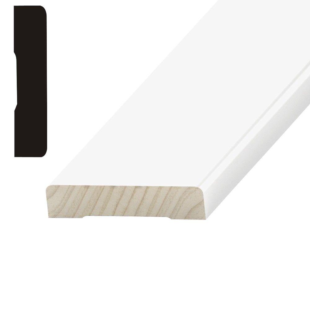
4 1/2 Casing
2' Colonial Casing 5/8' X 2' | 2-1/4' Colonial Casing 9/16' X 2-1/4' | 2-1/2' Colonial Casing 9/16' X 2-1/2' |
Old Sytle Colonial Casing 9/16' X 2-3/16' | C-20 Casing 9/16' X 2-1/2' | Wedge Casing 9/16' X 2-1/4' 9/16' X 2-1/8' |
Beaded Colonial Casing (C-1) 11/16' X 3-1/2' | 3-1/4' Fluted Casing (C-10) 9/16' X 3-1/4' | Mixon Casing 9/16' X 2-1/8' |
3-1/2' Colonial Casing (C-13) 5/8' X 3-1/2' | C-11 Casing 1-1/8' X 3-1/2' | C-3511 Casing 11/16' X 3-1/2' |
C-3011 Casing 11/16' X 2-7/8' | C-322 Casing 9/16' X 2-1/2' | C-522 Casing 9/16' X 3-1/2' |
C-422 Casing 1-1/8' X 3-1/2' | C-22 Casing 1-1/8' X 4' | C-3325 Casing 9/16' X 3-1/2' |
C-3250 Casing 9/16' X 2-1/2' | Brick Mould 1-1/8' X 2' | C-196 Casing 1-3/16' X 3-1/2' |
PC-1 Casing 1/2' X 3-1/8' | PC-20 Backband for PC-1 Casing 7/8' X 13/16' | 3-1/4' Beaded Casing 11/16' X 3-1/4' |
3-7/8' Special Beaded Casing 9/16' X 3-7/8' | Plynth for 3' Beaded Casing 13/16' X 3-1/2' | 4' Beaded Casing 1-1/16' X 4' |
4-1/4' Corner Block for Beaded Casing 1-5/16' X 4-1/4' | C-25 Pilaster 11/16' X 5-1/4' | C-16 Casing 11/16' X 5-1/4' |
C-14 Casing 11/16' X 3-1/2' | C-14 Casing Reversed 11/16' X 3-1/2' | 4-1/4' Fluted Casing (C-41) 11/16' X 4-1/4' |
C-17' Casing 11/16' X 3-1/2' | 5-1/4' Fluted Casing (C-51) 11/16' X 5-1/4' | 5-1/4' Beaded Casing (C-51R) 11/16' X 5-1/4' |
4 1/2 Casing Make Up Torque
For buttress thread casing connections in sizes 4 1 / 2 through 13 3 / 8 OD, makeup torque values should be deter- mined by carefully noting the torque required to make up each of several connections to the base of the triangle; then using the torque value thus established, make up the balance of the pipe of that particular weight and grade in the string. Browse 2 1/2' Face x 1/4” Liquid Filled Stainless Case - Brass Internals U-Clamp in the Seal Fast, Inc. Catalog including Item #,Face Size,Case Size,Pressure Range,Mounting Type,Case Material,List Price. TM 306 11/16 x 2-1/4 9/16 x 2-1/4 TM 352 5/8 x 2-1/2 TM 346 5/8 x 2-1/4 CASING MOULDING PROFILES FJ FJ FJ FJ FJ FJ H FJ FJP 5/8 x 2-1/4 H 1/2 x 2-1/8 OV SP KA FJ H FJ H FJ H FJ SP Note: Actual Profile Sizes May Vary Depending On Wood Species.
A casing and bit size program must consider the problems described in the previous section in addition to the actual casing and bit size characteristics. These characteristics include the following items:
- casing inner and outer diameter
- coupling diameters
- hit sizes
A working knowledge of the relationship of these variables is important for the selection of a viable geometry program.
Pipe Selection. Casing availability is a priority consideration in hole geometry selection. High-strength casing often required for deep wells may have a small inner (drift) diameter that will influence subsequent casing and bit size selection. Unfortunately, supply and demand cycles in the pipe industry may control the pipe design rather than engineering considerations.
The outer diameter (OD) of the casing is available in numerous sizes. The drift diameter, which is smaller than the inner diameter (ID), controls the bit selection for the open hole below the casing. (The drift diameter is described in further detail in Chapter 11.) As heavier-weight pipe is required to meet certain design specifications, the available drift diameter is reduced. A rule-of-tbumb that has proven satisfactory in most field cases is to allow I in, of wall thickness to achieve a suitable design without resorting to the use of ultra-high-strength pipe (V-I50, 500-155, S00-I40, etc.). As an example, 9s/swn. casing can usually be designed properly if 8s/s-in. drift diameters arc allowed.
Hole geometry selection with the bottom-to-top approach may dictate the drift diameter of the casing as the controlling criteria. The options for this design logic are as follows:
- try to design the pipe under the specific drift and outer diameter conditions
- use high-strength materials
- use special drift pipe available from some manufacturers
- as a last resort, pipe manufacturers will prepare a special pipe design based on minimum drift requirements by enlarging the wall thickness and outer diameter
The fourth option is occasionally required in hydrogen sulfide environments where low-strength metals must be used.

Coupling Selection. Pipe couplings are generally designed to satisfy requirements such as burst, collapse, tension, and sealing effectiveness. However, coupling diameters may be a design guideline in some wells. Table 6-2 shows the outer diameter of various types of couplings and pipe sizes. API couplings are normally 1 in. larger than the pipe in sizes greater than 75/s in.
Significant advantages are often provided by using premium couplings. These couplings usually have clearances less than comparable API connections and. as such, will occasionally allow the use of smaller pipe in a well. In many cases, more expensive premium couplings can clearly reduce the total well cost by allowing smaller pipe and hole geometries. In Fig. 6— lb, the hole geometry would not be difficult to achieve if premium couplings were used, whereas clearances might be unacceptable if API couplings were used.
Bit Size Selection. Sizing the bit program is dependent on the required casing sizes. Bits are available in almost any desired size range. However, nonstandard bits or unusual sizes may not possess all of the desirable features, such as center jet or gauge protection characteristic^ In addition, bit selec-
Table 6-2 Clearances for API and Various Premium Proprietary Couplings
Coupling Size, in.
Table 6-2 Clearances for API and Various Premium Proprietary Couplings
Coupling Size, in.

Pipe Size, in. | LTC (API)1 | SFf | VAIVF | IJ-4S1 |
4 'A | 5.0 | 4.59 | 5406 | 5.I50 |
5 | 5.563 | 5.09 | 5.391 | 5.875 |
5 Vi | 6.050 | 5.625 | 5.891 | 6.375 |
6-Vs | 7.390- | 6.75 | 7.390 | 7.390 |
7S4 | 8.50 | 7.75 | 8.504 | 8.50 |
8s/s | 9.625 | 8,75 | 9.625 | 9.625 |
9% | 10.625 | 9.75 | 10.625 | ! 0.625 |
im | 1 1 750 | 10.875 | 11,748 | — |
'long thread and coupling (same diameter as STC or BTC) | 'VAM (Vdllourec) | |||

4 1/2 Casing Id
- sup>:SFJ iHydiil)'IJ-4S (NL Atlas Bradford)
- sup>:SFJ iHydiil)'IJ-4S (NL Atlas Bradford)
4 1/2 Casing Scraper
Table 6-3 Size Availability for Various Hughes Insert Tooth, Journal Bearing Bits
Hughes Bit Designation (IADC Code)
Table 6-3 Size Availability for Various Hughes Insert Tooth, Journal Bearing Bits
Hughes Bit Designation (IADC Code)
Bit Size, | J-44(6,1,7) | ||||
m. | >22(6,1,7) | J-33(5,3,7) | 1-55(6,3,7) | 1-77(7,3,7) | j-99(8,3,7) |
4V4 | X | ||||
57A | X | X | |||
6 | X | X | |||
6Vh | X | X | |||
61A | X | X | |||
m | X | X | X | X | |
.6% | X | ||||
77/x | X | X | X | X | X |
8% | X | ||||
8'A | X | X | X | X | X |
8M | X | X | X | X | X |
9'/j | X | X | X | ||
m | X | X | X | X | |
10% | X | X | |||
11 | X | ||||
12 % | X | X | X | X | |
17 >/2 | X |
tion and availability become more difficult in odd or small bit sizes (less than 6.5 in.}.
Table 6-3 illustrates size availability for Hughes insert tooth bits. Bit sizes less than 6'/i in. restrict bit type selection. In addition, bit selection is restricted for sizes greater than 12Vi in.
Standard Bit-Casing Combinations
Fig. 6-3 can be used to select the easing and bit sizes required to fulfill many drilling programs. To use the chart, determine the casing or liner size for the last size of pipe to be run. The llow of the chart indicates hole sizes that may be required to set that size of pipe (i.e., 5-in, liner inside or b'A-in. hole).
Solid lines indicate commonly used bits for that size pipe and can be considered to have adequate clearance to run and cement the casing or liner (i.e., S'/i-in. casing in a V/x-'m. hole). The broken lines indicate less commonly used hole sizes. The selection of one of these broken paths require« that special attention be given to the connection, mud weight, cementing, and doglegs.
Continue reading here: Questions
Was this article helpful?